Attempting a DIY CNC Mill
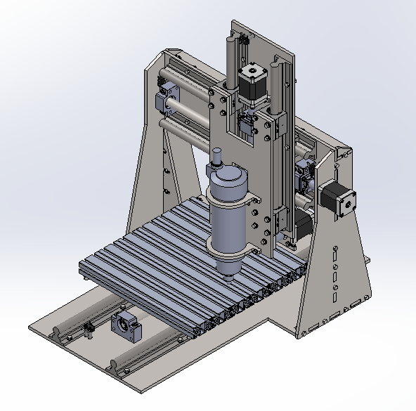
From 2014 to 2016, I worked on and off for about two years on building a table-top 3-axis CNC milling machine. The goal was ambitious: cut aluminum parts with at least 5 thou (0.127 mm) of positioning accuracy, all for under $1000.
Project Requirements
From the start, I defined a clear set of requirements to guide the design:
- Work volume: At least 20×20×20 cm
- Material capability: Cut aluminum (forming chips without losing position accuracy)
- Positioning accuracy: ≤ 5 thou
- Budget: ≤ $1000
- Power source: Standard 120VAC @ 60Hz North American wall socket
- Workpiece support: Handle at least 5 kg
- Safety: Enclosed working area to contain cuttings and keep hands out
Build from Scratch or Modify?
Early on, I considered two approaches:
- Buy an existing manual mill and convert it to CNC
- Build a machine from scratch
While modifying an existing mill would have been faster, I chose to build from scratch. The learning opportunity was the main draw-I wanted to understand every part of the machine, from the mechanical frame to the motion control electronics. This also gave me complete control over the design to meet the specific requirements.
Motion System Design
The CNC needed three independent axes (X, Y, Z) with precise, repeatable movement. I focused first on designing a single axis, knowing the same choices would apply to all three.
Actuator Selection
For moving each axis, I evaluated two main options:
Option A: DC brushed motor + linear amplifier + encoder + ball screw
- Pros: Continuous position control, simpler electronic hardware
- Cons: More design effort, no readily available firmware, must develop from scratch
Option B: Stepper motor + stepper driver + ball screw
- Pros: Mature open-source hardware and firmware (grbl), many existing resources, built-in closed-loop stepping
- Cons: Discretized position control, possibility of missed steps under high load
I chose Option B with stepper motors. The availability of open-source solutions like grbl meant I could get the machine working faster and focus on the mechanical design. I selected the gShield driver board, which integrates TI DRV8818 drivers and works with grbl firmware on an Arduino.
Linear Motion: Ball Screws
To convert rotary motion to linear motion, I considered:
| Option | Pros | Cons |
|---|---|---|
| Timing belt | Inexpensive, simplest, no backlash | Least axial rigidity |
| Lead screw | Low-moderate cost, high rigidity | Moderate backlash |
| Ball screw | Very low backlash, high rigidity | Expensive |
For the required positioning accuracy under cutting loads, ball screws were the clear choice despite the higher cost. The trade-off was necessary to achieve the 5 thou accuracy target. To stay within budget, I sourced ball screws from sellers on eBay.
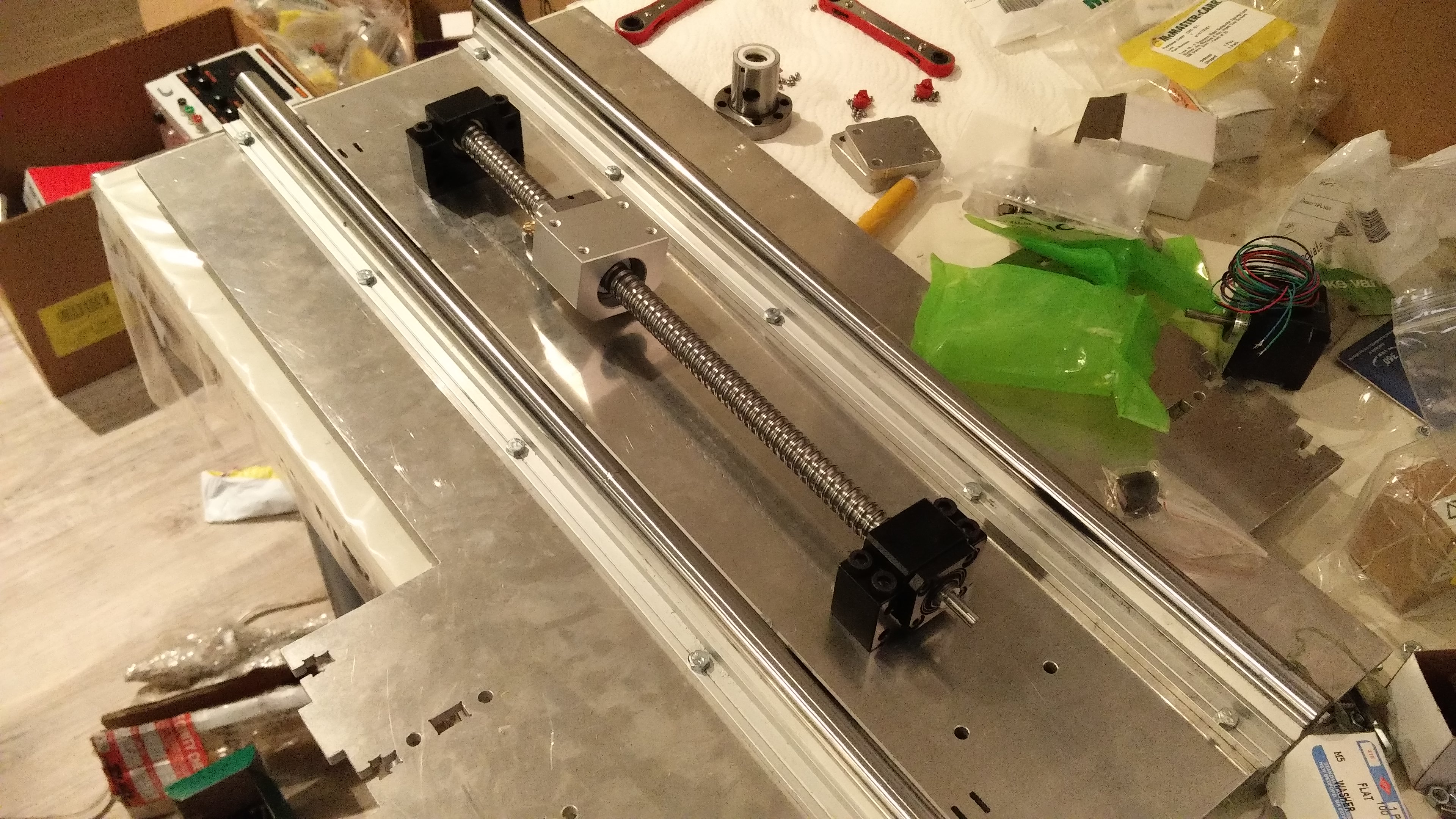 The Y-axis ballscrew assembly - the ball screw is mounted to the frame with the stepper motor coupled at one end
Spindle Selection
The spindle needed to cut aluminum within the budget and power constraints. This was one of the most challenging decisions.
Power Requirements
Most spindles capable of cutting aluminum use 3-phase induction motors requiring a Variable Frequency Drive (VFD). However, most available VFDs needed 220VAC input, which would require a step-up transformer from the 120VAC wall socket-adding cost and complexity.
I used FSWizard, a free online cutting calculator, to estimate power requirements. By testing various end mill sizes, cutting depths, and feed rates, I found that:
- A 0.4kW spindle could handle typical aluminum cuts with material removal rates of 22-29 cm³/min
- The required spindle power for my test cases peaked at 0.37kW, within the 0.4kW limit
- This spindle used a 48V DC power supply instead of a VFD, eliminating the transformer requirement
 FSWizard sample calculation for spindle power requirements
Cost Comparison
| Spindle Set | Cost |
|---|---|
| 1.5kW spindle + VFD + accessories | ~$480 (transformer not included) |
| 0.8kW spindle + VFD | ~$340 (transformer not included) |
| 0.4kW spindle + DC power supply + controller + mounting bracket | ~$175 |
 FSWizard calculations for 0.4kW spindle performance
The 0.4kW option was the only one that fit comfortably within the budget while meeting the technical requirements.
Motor Sizing
With the spindle selected, I needed to size the stepper motors for each axis.
Torque and Power Calculations
Using FSWizard, I calculated cutting forces for various scenarios. The stepper motor needed to:
- Resist the cutting force through the ball screw
- Provide sufficient speed for the desired feed rates
The key formulas were:
- Torque: T = (F × l) / (2π × e)
- F: cutting force (N)
- l: ball screw lead (m)
- e: screw efficiency (~90%)
- Speed: ω = f / l
- ω: motor rotation speed (rad/s)
- f: feed speed (m/s)
- l: lead (m)
- Power: P = (F × f) / (2π × e)
From my calculations across multiple cutting scenarios, the maximum required motor power was approximately 0.56W. Applying a 1.5x safety margin (for real-world variations), each motor needed at least 0.84W of power.
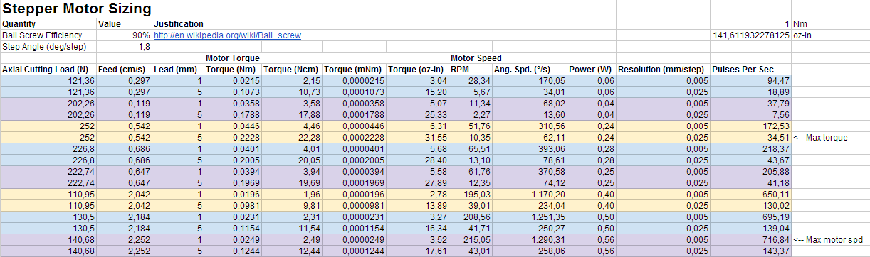 Stepper motor power requirements across different cutting scenarios
Voltage Considerations
The gShield supports 12-30V input. Stepper motors have a rated voltage for steady-state operation, but can accept higher voltages during acceleration. Higher input voltage increases torque at lower speeds and helps the motor reach steady state faster, but can cause:
- Vibration problems
- Resonance issues
- Excessive heat
I planned to test different voltages within the gShield’s range to find the optimal balance. However, I did not initially account for the heat generated by the gShield itself. During testing of a single axis, the shield kept going into thermal shutdown. It took me a while to diagnose this as a heat dissipation issue rather than a power or configuration problem.
Control System
The control architecture was straightforward:
1
2
3
Computer → Gcode Sender (Otto Hermansson's open-source tool)
       → USB → Arduino + gShield (running grbl)
       → Stepper motors + drivers
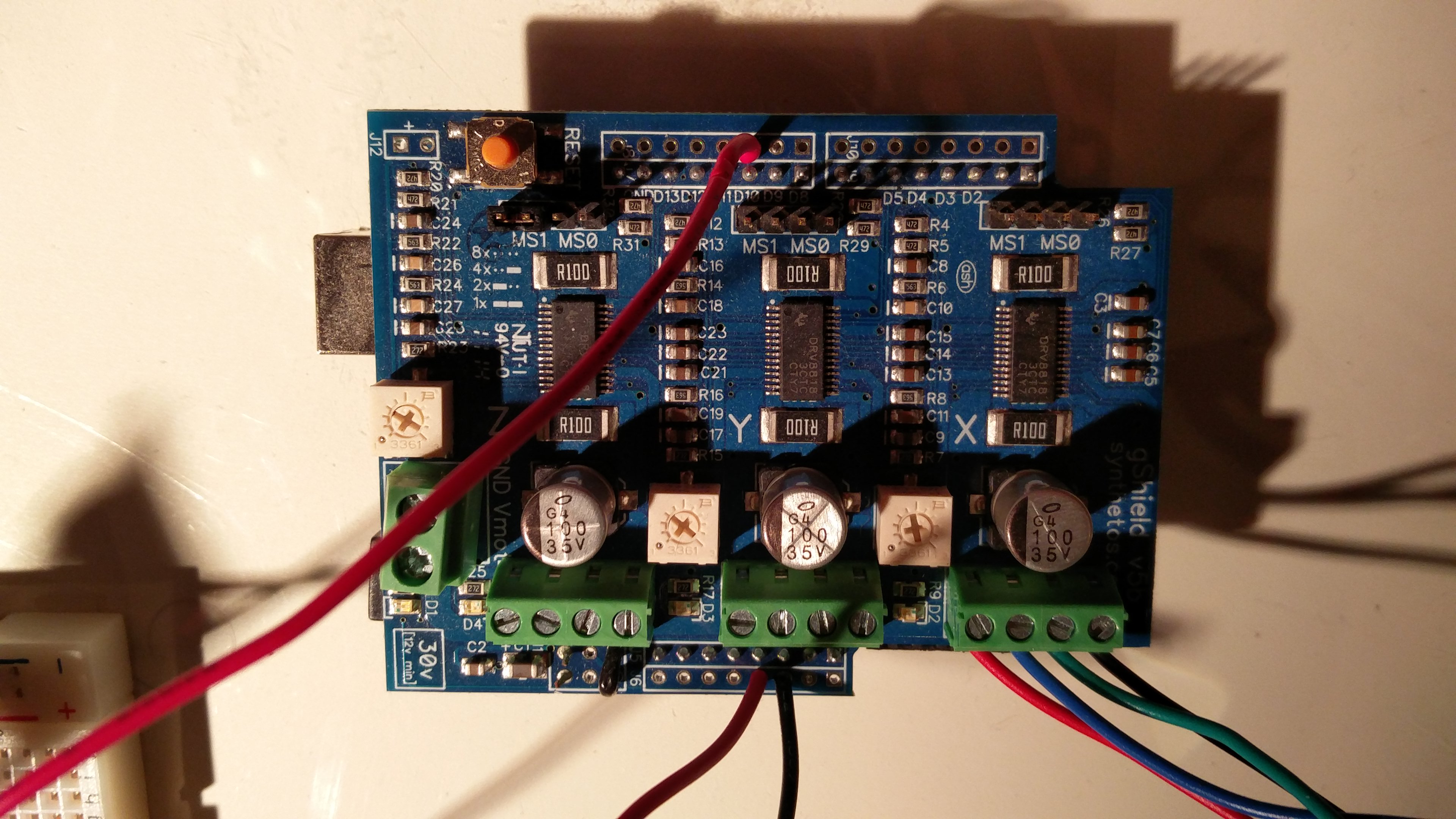 Arduino plugged into the gShield stepper motor driver board
This setup provided:
- USB connectivity for easy computer control
- Flexibility of a modern microcontroller platform
- Open-source firmware that could be modified if needed
Build Progress
The project progressed through several phases:
- Design Phase: Requirements definition, component selection, calculations
- Prototyping: Testing stepper motors, drivers, and mechanics
- Assembly: Building the machine frame and installing axes
- Electronics: Wiring the gShield, limit switches, spindle control
Lessons Learned
What worked well:
- The stepper motor design and grbl firmware provided a solid foundation for motion control
- FSWizard was invaluable for estimating cutting parameters without deep machining expertise
- Building from scratch provided deep understanding of CNC design principles
What broke the design:
The project ultimately failed due to two critical issues:
First, the Chinese-made eBay ball screws had super high friction-even when under no load and not mounted to anything. This completely threw off all my calculations. No amount of motor sizing could overcome the mechanical resistance of the screws themselves. To fix this would have required specing out new, higher-quality ball screws, but that would have meant redesigning the mount points to fit different dimensions. I didn’t bother. Saving money on cheap ball screws invalidated months of careful motor sizing and power calculations.
Second, I had not accounted for heat dissipation from the gShield. The shield kept going into thermal shutdown during single-axis testing, which took me a while to diagnose.
Current Status
The machine never reached a fully functional state. The Chinese ball screws were so problematic that I never completed the full assembly. The project effectively ended in August 2016 after two years of on-and-off work, when I lost interest in re-designing the mount points for better screws.