Fixing 3D Rotation in PicToBrick, a LEGO Mosaic Generator
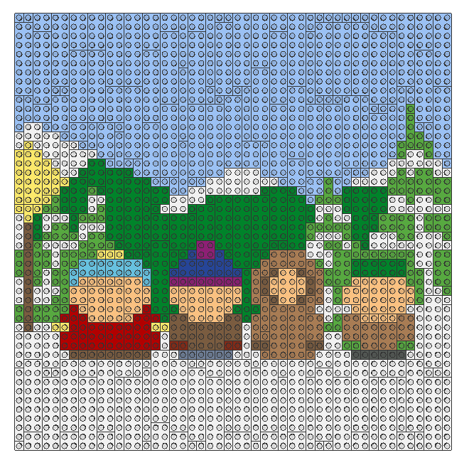
For a while, I was making LEGO mosaics.
The process started as pixel art: draw an image on a grid, treat each LEGO piece as a pixel, and size the image to fit a LEGO baseplate. I then used BrickifyFX, a PicToBrick fork to turn that image into a mosaic.
BrickifyFX does more than place one LEGO piece for every pixel. Where possible, it merges adjacent regions of the same colour into larger pieces. That makes the result more practical to build and usually looks better than a sea of single studs.
Exporting to LDraw
I wanted to view the generated mosaics in a CAD tool, so I exported them to LDraw.
LDraw stores more than a part number and a position. It also needs enough information to describe the part’s orientation in three-dimensional space. That matters when BrickifyFX has combined pixels into rectangular pieces that need to be rotated by 90 degrees.
The original exporter wrote the pieces at the correct locations, but it did not correctly include their rotations. A rotated rectangular piece could therefore appear with the wrong orientation after export.
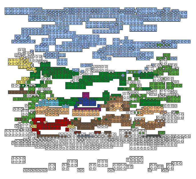
The fix required doing a little linear algebra.
Rotating a Piece in 3D
A rotation is a transformation of coordinates.
For this exporter, the pieces lie on the X-Z plane. Y is the vertical axis, so rotating a flat mosaic piece means rotating it around Y. In other words, the piece turns left or right while remaining flat against the baseplate.
The code first converts the rotation from degrees to radians because Java’s trigonometric functions use radians:
1
2
3
private static double convertDegreesToRadians(int degrees) {
    return degrees * Math.PI / 180;
}
The rotation matrix is then:
1
2
3
4
5
6
double[][] rotationMatrix = {
    { Math.cos(rotationRad), 0, Math.sin(rotationRad), 0 },
    { 0, 1, 0, 0 },
    { -Math.sin(rotationRad), 0, Math.cos(rotationRad), 0 },
    { 0, 0, 0, 1 }
};
The important values are the sine and cosine terms. Together, they rotate the X and Z coordinates by the requested angle while leaving Y unchanged.
The final row and column make this a 4×4 transformation matrix. The extra coordinate is what allows rotation and translation to be represented in the same kind of matrix.
Moving the Piece into Position
Rotation alone is not enough. The part also has to be placed at the correct location in the mosaic.
1
2
3
4
5
6
double[][] translationMatrix = {
    { 1, 0, 0, 0 },
    { 0, 1, 0, 0 },
    { 0, 0, 1, 0 },
    { width / 2.0, 0, -height / 2.0, 1 },
};
This matrix shifts a piece by half its width and half its height.
The signs might look unusual at first:
1
{ width / 2.0, 0, -height / 2.0, 1 }
That is because of the coordinate conventions used by the exporter: right is positive X, while moving down the mosaic is negative Z. The translation moves the piece from its local origin to the position expected by LDraw.
Combining Transformations
The exporter combines matrices with ordinary matrix multiplication:
1
2
3
4
5
6
7
8
9
10
11
12
13
14
15
16
17
18
19
20
21
22
23
24
25
private static double[][] mmult(double[][] a, double[][] b) {
    int aRows = a.length;
    int aColumns = a.length;
    int bRows = b.length;
    int bColumns = b.length;

    if (aColumns != bRows) {
        throw new IllegalArgumentException(
            "A:Rows: " + aColumns +
            " did not match B:Columns " + bRows + "."
        );
    }

    double[][] c = new double[aRows][bColumns];

    for (int i = 0; i < aRows; i++) {
        for (int j = 0; j < bColumns; j++) {
            for (int k = 0; k < aColumns; k++) {
                c[i][j] += a[i][k] * b[k][j];
            }
        }
    }

    return c;
}
Matrix multiplication lets several operations become one transformation that can be written to the LDraw file.
This code uses row vectors: a point is treated as being on the left of the matrix. That means the transformations are applied from left to right.
For an ordinary rectangular piece, the exporter combines rotation and translation like this:
1
return mmult(rotationMatrix, translationMatrix);
Conceptually, the piece is rotated first and then translated into place:
1
2
3
4
5
piece coordinates
        ↓
rotate around the Y axis
        ↓
move to its LDraw position
Handling Corner Pieces
Corner-style pieces need one extra adjustment.
Their local origin is not centred in the same way as the ordinary rectangular pieces. Rotating them directly would rotate them around the wrong point and leave them offset from the intended mosaic grid.
The exporter compensates with an additional translation:
1
2
3
4
5
6
double[][] cornerTranslationMatrix = {
    { 1, 0, 0, 0 },
    { 0, 1, 0, 0 },
    { 0, 0, 1, 0 },
    { width / 4.0, 0, height / 4.0, 1 }
};
The quarter-width and quarter-height offset shifts the local coordinates so that the effective centre of rotation matches the centre used by a 2×2 piece.
For those pieces, the final transformation is:
1
2
3
4
return mmult(
    mmult(cornerTranslationMatrix, rotationMatrix),
    translationMatrix
);
Because the code uses row vectors, this applies the transformations in this order:
1
2
3
4
5
adjust the corner piece's local position
        ↓
rotate the piece
        ↓
translate it into the mosaic
The corner adjustment was based on the corner orientations I had available to test. It should generalise to similar pieces, although other corner orientations would need additional verification.
Correctly Oriented Exports
After adding the transformation matrices, the exporter could preserve both a piece’s position and its rotation.
That meant a mosaic generated from pixel art could be exported to LDraw and viewed in CAD with the larger merged pieces facing the correct direction. The change was small in terms of code, but it was the difference between an export that was merely recognisable and one that matched the generated LEGO mosaic.